Update: This article has been updated to show the features of the Spatial Mic Converter Plugin Version 1.7.1
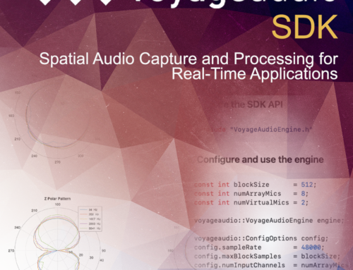
The Spatial Mic Converter plugin transforms the raw audio signals from both Spatial Mic Dante and Spatial Mic USB/ADAT, to a format that is audio production ready. The audio output decoded from Spatial Mic Converter can be first or second order ambisonics in AmbiX or Fuma, mono or stereo virtual mics, or up to 7.1.4 surround. To accomplish this, Spatial Mic Converter uses an internal 64-channel filter matrix and measurements from an anechoic chamber.

Spatial Mic Converter is available as VST3, AAX, and AU, and requires a host that supports multi-channel audio tracks such as Reaper, Pro Tools, Nuendo, Logic Pro, Cubase Pro, or Plogue Bidule. The plugin and demo sessions are available as free downloads to test system compatibility.
Link: Download Spatial Mic Converter & free listening sessions
Spatial Mic Converter offers the capability to change the microphone’s aim at the point in space where the audio was recorded. This is useful when aligning audio position with 360 video, aiming the mic at specific sounds that should be in front of the listener, or used in combination with the virtual mic output stage to focus directional polar patterns at different parts of the soundfield.
The ambisonic output can be sent to a variety of plugins from SSA, Blue Ripple Sound, IEM, SPARTA and others for further processing while mono or stereo outputs can be used with standard audio production plugins. The surround outputs can be used as sound bed tracks in Dolby Atmos® sessions or routed directly to the surround bus of choice.
Skip ahead to:
Surround Outputs and Channel Ordering
Usage
The built-in Spatial Mic Converter filters are specific to the raw signals from Spatial Mic and as such are only valid for Spatial Mic product family. Note that the plugin also offers the ability to load custom 64-channel .wav filters for any 8-channel second order microphone, however this is beyond the scope of this article. Spatial Mic Converter should be the first plugin in your signal chain when processing the raw signals from Spatial Mic.
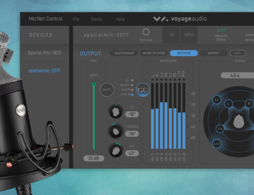
Controls & Interface

Interface
There are 3 main sections to the Graphical User Interface.
Processing
This section displays and allows user input to change mic orientation, rotation, filter, visualization view, and more.
Inputs
Shows the unprocessed level with clip indication for each of the 8 capsules.
Outputs
Shows the processed output level with clip indication. Channel ordering changes based on output format selection.
Controls
Mic
Select which model Spatial Mic captured the audio tracks being converted. This will load the appropriate microphone specific files in the Filters dropdown menu below.
- Dante
- USB/ADAT
Filter
Each microphone model has its own filters to transform the raw capsule output.
- Spatial Mic USB/ADAT: Type X and Type Y filters offer the latest in decoding options and were carefully created in an anechoic chamber to take into account microphone geometry. Many people prefer Type X filtering for its high spatial resolution or Type Y for its more diffuse, flat response.
Type 1 and Type 2, along with their complementary low noise (LN) versions, offer an alternative filtering to complement low noise recordings and other tonal choices. Type 1 and Type 2 were the original filters shipped with Spatial Mic USB / ADAT. - Spatial Mic Dante: Type A and Type B filters were carefully crafted in an anechoic chamber specifically for Spatial Mic Dante. Type A filtering exhibits high spatial resolution, while Type B offers a more diffuse, flat response.
- Custom: There is also the option to load a custom filter (64-channel .wav expected)
Tilt
Tilts the Spatial Mic recording direction up and down. Rotation and roll are maintained when tilting.
Range: ±45°
Default & Reset: 0°
Rotation
Rotates the Spatial Mic recording direction left and right. Tilt and roll are maintained when rotating.
Range: ±180°, continuous
Default & Reset: 0°
Roll
Rolls the Spatial Mic recording direction side to side. Tilt and rotation are maintained when rolling.
Range: ±45°
Default & Reset: 0°
Highpass
Activates a selectable frequency high pass filter, useful to cut wind noise or other low frequency artifacts.
Options: Off, 80Hz, 120Hz, 160Hz
Orientation
It is often desirable for the orientation to correspond with the real-life position of the microphone.
Normal: The Spatial Mic capsule array is aimed up.
End-Fire: The Spatial Mic capsule array is aimed forward.
Inverted: The Spatial Mic capsule array is aimed down.
View
Switch between views to display different visualization options for the incoming audio. The visualization options can be enabled or disabled by right clicking on images of the heads in view one and then selecting the appropriate menu item.
View One: This displays the Direction Of Arrival information around the heads. This will help to understand where different sounds in the soundfield are coming from, with the brighter red color indicating the higher signal levels.

View Two: The Power Map view displays a projection of the 3D sphere around the microphone with larger circles representing sounds of greater power and brighter colors at higher frequencies. The frequency range legend can be shown by right clicking on the power map and then selecting the appropriate menu item.

Trim
Controls input level. Plugin processing may increase the signal level. If output meters clip, you may need to reduce trim.
Range: -20dB to +20dB
Default & Reset: 0dB
Outputs
Selects the output type. This should correspond to the input type of the next plugin in the signal chain. Note that the output types differ in channel count, ordering and level weighting.
Options: ambiX 2nd Order, ambiX 1st Order, FuMa 2nd Order, FuMa 1st Order, Virtual Mic, Mid-Side, and Surround.
R Channel Output Note: The ‘R’ channel is silenced by default unless the Tilt control is adjusted. By clicking on the ‘R’ channel label of the output meter, Spatial Mic Converter plugin will generate the R channel from the W channel. When enabled the R icon will change to a green color. This may enhance the presence of height to recordings that are mostly horizontal, however it is best to use your ears to confirm this is the right choice.

Output Options
Virtual Mic Output
The Virtual Mic output section enables the creation of mono or stereo microphone polar patterns that can be aimed in the sound field using the plugin tilt, rotation and roll controls. The virtual mic interface is shown on the plugin GUI when it is selected under the Outputs dropdown menu as shown below.

Polar patterns are created using three controls:
Type
Four different types of virtual mic decoding are available: In-Phase, Basic, max rE and Figure 8. Within each type, the pattern and width can be adjusted to manipulate the stereo field and polar pattern shape.
Figure 8: Traditional Omni → Cardioid → Figure 8 microphone patterns
Basic: Virtual mic patterns capable of second order cardioid (pattern = 2)
Max rE: Maximizes energy concentration vector by focusing energy signals in the direction of interest.
In-Phase: Full side-lobe suppression with no out-of-phase components

Pattern
The pattern control is continuously adjustable and changes the focus of the pattern from omnidirectional to a narrow pattern based on the virtual mic type selected. The pattern control can also be thought of as changing the ‘order’ from 0→1 for Figure-8 and 0 → 2 for all other pattern types.
Width
The width control duplicates the polar pattern created and offsets their aim by the selected angle to create a virtual stereo microphone pair. The stereo width angle is continuously variable from 0° → 180°. When Width = 0, a mono signal is created.
Presets
Spatial Mic Converter has built-in presets to quickly audition different configurations. The following chart shows the characteristics of the presets that utilize the virtual mic output stage.

Mid-Side Output
Like the other virtual stereo outputs the Mid-Side stereo output is decoded from the 8 capsules and steerable anywhere in the soundfield. The Mid-Side stereo output section also includes pattern, balance and output adjustments.

Mid Pattern
The pattern control of the Mid-Side output changes the polar pattern of the mid component from tight cardioid all the way to omni-directional.
Balance
The balance adjusts the level balance between the mid and side components to manipulate the stereo width of the recording.
Output
The output can be post Mid-Side matrix network as left right stereo or pre Mid-Side matrix network as the mid pattern and side pattern each on separate channels to be further decoded later.
Surround Output
The surround section includes six different output configuration options that are selectable in the format drop down menu. The channel assignments are listed below for each format option to ensure proper routing.

The numbers in the surround format name indicate the number of channels and type. For example, the numbers to the far left indicate the number of main channels, the middle numbers the number of Low Frequency Effects (LFE) and the numbers to the right indicate the top or overhead channels.
A 7.1 system would normally have 7 main channels and one LFE, while a 7.1.2 (Dolby Atmos) would have 7 main channels, 1 LFE and 4 top channels to increase immersion.
5.1 (ITU 775) surround format

| 5.1 Surround Sound | ||||||
|---|---|---|---|---|---|---|
| Channel # | 1 | 2 | 3 | 4 | 5 | 6 |
| Channel Name | L | R | C | LFE | Ls | Rs |
| Azimuth | -30° | 30° | 0° | 0° | -110° | 110° |
| Elevation | 0° | 0° | 0° | 0° | 0° | 0° |
5.1.2 surround format

| 5.1.2 Surround Sound | ||||||||
|---|---|---|---|---|---|---|---|---|
| Channel # | 1 | 2 | 3 | 4 | 5 | 6 | 7 | 8 |
| Channel Name | L | R | C | LFE | Ls | Rs | Ltm | Rtm |
| Azimuth | -30° | 30° | 0° | 0° | -110° | 110° | -73.26° | 73.25° |
| Elevation | 0° | 0° | 0° | 0° | 0° | 0° | 58.5° | 58.5° |
5.1.4 surround format

| 5.1.4 Surround Sound | ||||||||||
|---|---|---|---|---|---|---|---|---|---|---|
| Channel # | 1 | 2 | 3 | 4 | 5 | 6 | 7 | 8 | 9 | 10 |
| Channel Name | L | R | C | LFE | Ls | Rs | Lt | Rt | Lts | Rts |
| Azimuth | -45° | 45° | 0° | 0° | -110° | 110° | -39° | 39° | -140° | 140° |
| Elevation | 0° | 0° | 0° | 0° | 0° | 0° | 38° | 38° | 38° | 38° |
7.1 surround format

| 7.1 Surround Sound | ||||||||
|---|---|---|---|---|---|---|---|---|
| Channel # | 1 | 2 | 3 | 4 | 5 | 6 | 7 | 8 |
| Channel Name | L | R | C | LFE | Lm | Rm | Ls | Rs |
| Azimuth | -45° | 45° | 0° | 0° | -90° | 90° | -135° | 135° |
| Elevation | 0° | 0° | 0° | 0° | 0° | 0° | 0° | 0° |
7.1.2 surround format

| 7.1.2 Surround Sound | ||||||||||
|---|---|---|---|---|---|---|---|---|---|---|
| Channel # | 1 | 2 | 3 | 4 | 5 | 6 | 7 | 8 | 9 | 10 |
| Channel Name | L | R | C | LFE | Lm | Rm | Ls | Rs | Ltm | Rtm |
| Azimuth | -45° | 45° | 0° | 0° | -90° | 90° | -135° | 135° | -80° | 80° |
| Elevation | 0° | 0° | 0° | 0° | 0° | 0° | 0° | 0° | 44° | 44° |
7.1.4 surround format

| 7.1.4 Surround Sound | ||||||||||||
|---|---|---|---|---|---|---|---|---|---|---|---|---|
| Channel # | 1 | 2 | 3 | 4 | 5 | 6 | 7 | 8 | 9 | 10 | 11 | 12 |
| Channel Name | L | R | C | LFE | Lm | Rm | Ls | Rs | Lt | Rt | Lts | Rts |
| Azimuth | -45° | 45° | 0° | 0° | -90° | 90° | -135° | 135° | -55° | 55° | -125° | 125° |
| Elevation | 0° | 0° | 0° | 0° | 0° | 0° | 0° | 0° | 30° | 30° | 30° | 30° |
Going Further
We hope you enjoyed this walk-through of the Spatial Mic Converter plugin. The ability to decode second order ambisonics, virtual mic patterns and surround sound opens up a wide array of possibilities. We encourage you to learn more about applications for Spatial Mic and Spatial Mic Converter, and invite you to try out Spatial Mic Converter for yourself with our free session downloads. Both Spatial Mic Dante and Spatial Mic USB/ADAT are available for purchase now.